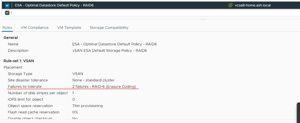
vSAN ESA is a software-defined offering designed to improve write performance, it’s a significant architecture change as opposed to the OSA model..vSAN ESA offers three default storage policies: RAID-1/FTT 1, RAID-5/FTT 1 and RAID-6/FTT 2
vSAN ESA Objects
Except for the snapshot layer, all the contents on the vSAN object are the same on ESA as well.
- VM Home Namespace: This object comprises all the VM’s configuration files, including VMX, NVRAM, and log files.
- VM Swap Object(s): When a VM is powered on, a swap object is created to manage the memory that is swapped out of the virtual machine.
- Virtual Hard Disk (VMDK): This object represents the VM’s virtual disk, housing the machine’s data.
- No Snapshots: Unlike the OSA model, the snapshot object for the VMDK is no longer available in ESA
- No Witness components are present in ESA.
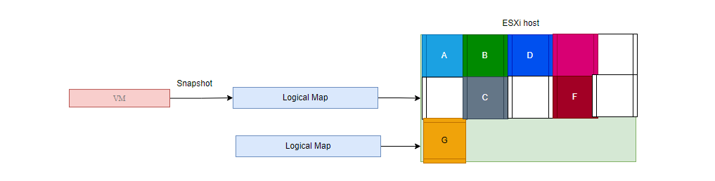
Concept of a VM Snapshot Chain in ESA
Whilst OSA uses the concept of delta disks to create snapshots, ESA uses a logical mapping approach to create an association with the blocks it’s changing within the VMDK object. This approach eliminates the need to traverse a snapshot chain to understand the current VM state, resulting in improved performance during VM snapshot operations. You can just think of this as a symbolic link or soft link in Linux.
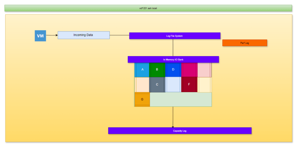
Log-structured filesystem (LFS)
OSA uses disk groups and it acts as a hybrid storage array – it’s got a cache tier and capacity tier. The incoming data or the hot data on the OSA model hits the cache tier first and when it reaches its 30 % capacity the contents are destaged to the capacity tier. In the OSA model, the cache tier is just reserved as a cache for incoming data and won’t contribute to the usable storage space on the vSAN datastore.
ESA gets rid of this two-tier system and places all disks into a single storage pool rather than the multiple disk group architecture in OSA. The ESA add the concept of a perf leg and a capacity leg. When a VM intends to do a write it goes to the perf leg on the esx hosts, and the logic used is to accumulate small I/o ( 128Kb) of data known as LFS in an in-memory buffer and gathers full stripes of data from LFS before it pushes data onto the capacity leg. As soon as the 128K of data ( full stripe ) is received, then only the vSAN starts the disk operation so there are no parity calculations of the contents in the capacity leg thus consider it a RAID 1 system. Once we get past the 128KB, vSAN will then compress all that data, apply the parity required and then destage all the capacity leg to all hosts. This is what’s known as IO amplification and this vastly improves write performance as all these happen on a single esx host and not on all other hosts than we saw in OSA. This reduces I/O amplification bit as all these happen on one host than all the hosts in the cluster is what makes the RAID 5/6 on the ESA much more performing than the OSA model
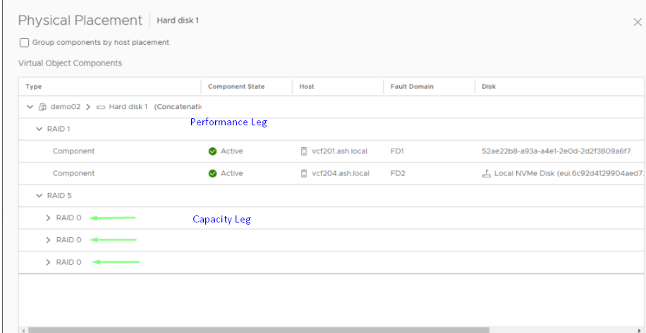
Unlike the OSA, where we had the cache tier, a loss of cache disk would have resulted in the total loss of that disk group on ESA, the Perf leg components are stored as a mirrored config for resilience and performance. In the below example, our VM storage policy FTT is set at 1.
vSAN Components
- Definition: A component is a smaller, discrete fragment of an object. Objects are divided into components to enhance data distribution across the cluster and streamline managing large volumes of data.
- Size Limitation: A single component can grow to a maximum size of 255 GB. If a VMDK file (virtual disk) is 300 GB, it cannot be stored as a single component because it exceeds the 255 GB limit. Instead, vSAN divides it into at least two components: one component of 255 GB and another of 45 GB. This is similar to adding an extent to a VMFS datastore.
- eg: If we have created a VM with RAID1, then the storage policy would have created two components on multiple ESXi hosts as shown below. As it’s raid 1, the components are getting mirrored across and of the two components, one component will be authoritative.
FTT 1 = 2 perf leg components & RAID-0/1 = 3 striped RAID-0 child components per mirror
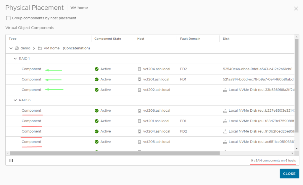
In the below example, our VM storage policy FTT is set at 2.
vSAN Witness
A witness is a metadata component and is used as a tiebreaker to avoid split-brain scenarios, also known as quorum in other technologies. There are no witness components in the ESA architecture.
Storage Policy Based Management ( SPBM )
- vSAN allows administrators to define storage policies that govern how components are distributed across the physical storage devices within the cluster. These policies are applied to objects and can control factors such as replication (for redundancy), striping (to boost performance), and fault tolerance.
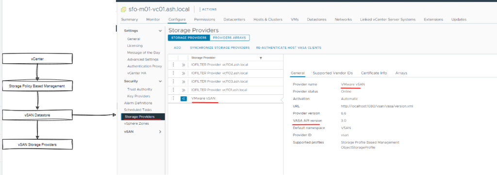
- SPBM advertises storage arrays’ data transfer capabilities thus responsible for bidirectional communication between the vCenter, ESXi and Storage Arrays. Storage providers communicate via an http interface between vCenter, ESXi and a storage array thus as shown the URL is registered with vCenter when a vSan is configured.
vSAN Storage Policy
Every virtual machine in a vSAN datastore needs a storage policy. If you don’t choose one when setting up a VM, vSAN will automatically use a default policy. This default policy is pretty basic—it can handle one failure without losing data (Failures to Tolerate of 1), uses a single disk stripe per object, and thin-provisions the virtual disks to save space.
By making your storage policies, you can adjust settings to match your specific needs, like adding more redundancy, improving disk performance, or choosing how storage is allocated such as the choice of RAID etc, how space efficient we need our array to be. This way, your virtual machines will run smoothly and efficiently, tailored to your specific requirements.
You can create multiple storage policies in vSAN based on your site’s disaster tolerance settings and the Failures to Tolerate (FTT) settings and these are applied to VMs.
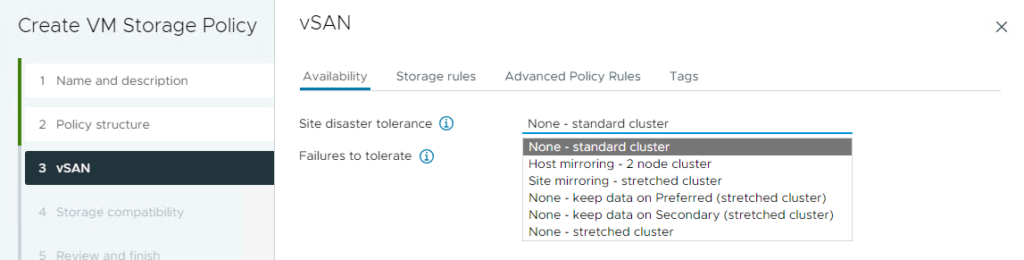
Site Disaster Tolerance:
This setting determines the type of vSAN environment you’re creating:
- Standard Cluster: A typical vSAN setup within a single site.
- Stretched Cluster: A vSAN configuration that spans two sites, providing data redundancy across locations for higher availability.
- Two-Node Cluster: A minimal setup where data is mirrored between two nodes, ideal for smaller environments that still need redundancy.
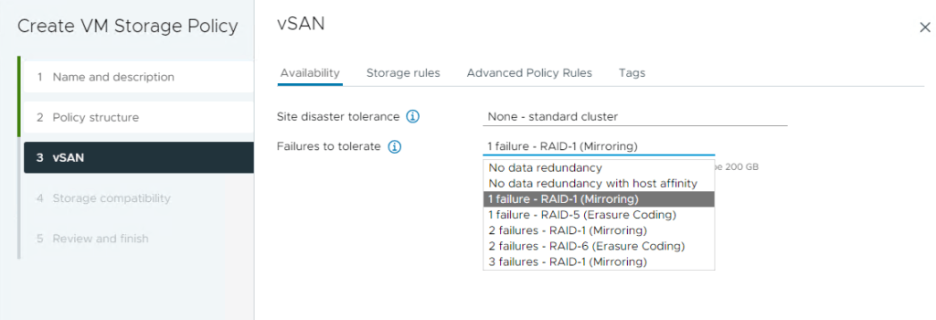
Failures to Tolerate (FTT):
This setting specifies how many failures (like disk or host failures) an object can withstand without losing data. For example:
- FTT of 1: The object can tolerate one failure.
- FTT of 2: The object can tolerate two failures, providing resilience.
- FTT of 3: The object can tolerate three failures, providing even greater resilience.
By combining these settings, you can create customized storage policies that align with your specific disaster recovery needs and the level of fault tolerance you require for your virtual machines.
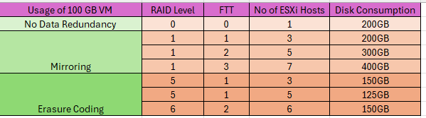
vSAN ESA Storage Policy Space Consumption
A table to show the provision and consumption of a 100GB VMDK file on vSAN datastore based on the Storage Policy rules.