
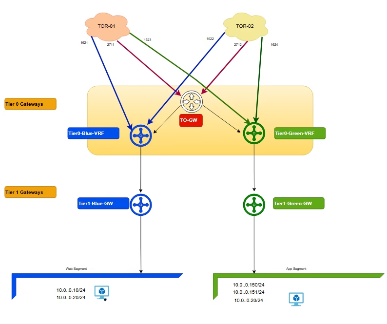
VMware NSX‑T provides VRF Lite functionality, allowing isolated routing domains within a single Tier‑0 Gateway. A VRF Tier‑0 Gateway is a child of a Parent Tier‑0 Gateway, effectively creating multiple “mini Tier‑0s” under one parent. This design enables secure tenant separation without duplicating physical infrastructure.
In this guide, we configure VRF Lite for two tenants (Blue and Green), including BGP sessions on upstream VyOS routers, NSX‑T segments, VRF uplinks, and validation.
The Problem Without VRF Lite
- Blue and Green tenant both use
10.10.10.0/24. - A standard Tier‑0 Gateway shares one routing table across all Tier‑1s.
- Overlapping prefixes cause conflicts, ambiguous route advertisements, and risk of leakage or blackholed traffic.
How VRF Lite Solves It
- Each VRF Tier‑0 Gateway is its own routing domain under the Parent Tier‑0.
- Blue and Green tenant get independent routing tables, BGP sessions, and uplinks.
- Even with the same subnet (
10.10.10.0/24), upstream routers see them as separate peers (unique ASN, interfaces).
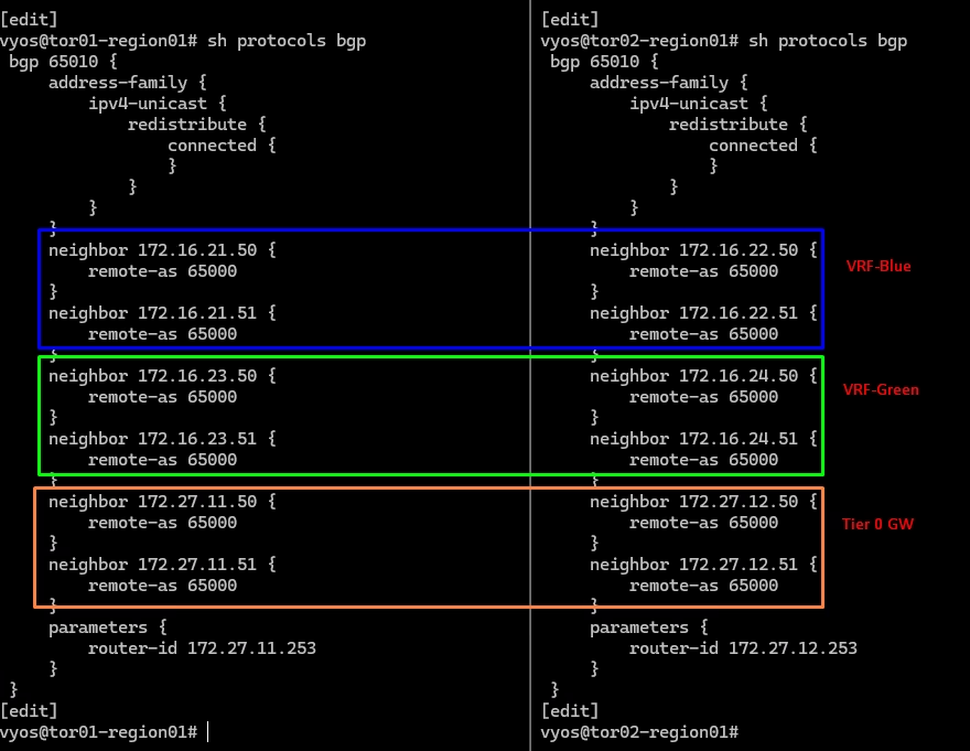
BGP Configuration on Physical Routers
On upstream routers, configure BGP sessions to match VRF Lite neighbours.
BGP Configuration on Physical Router for blue VRF
🔹 VyOS1 (VRF Blue, VLAN 1621)

set interfaces ethernet eth4 vif 1621 address 172.16.21.253/24
set interfaces ethernet eth4 vif 1621 description tenant-vrf-blue-uplink01
set interfaces ethernet eth4 vif 1621 mtu 9000
set protocols bgp 65010 neighbor 172.16.21.50 remote-as ‘65000’
set protocols bgp 65010 neighbor 172.16.21.51 remote-as ‘65000’

🔹 VyOS2 (VRF Blue, VLAN 1621)

set interfaces ethernet eth3 vif 1622 address 172.16.22.253/24
set interfaces ethernet eth3 vif 1622 description tenant-vrf-blue-uplink02
set interfaces ethernet eth3 vif 1622 mtu 9000
set protocols bgp 65010 neighbor 172.16.22.50 remote-as ‘65000’
set protocols bgp 65010 neighbor 172.16.22.51 remote-as ‘65000’BGP Configuration on Physical Router for Green VRF
🔹 VyOS1 (VRF Green, VLAN 1623)

set interfaces ethernet eth3 vif 1623 address 172.16.23.253/24
set interfaces ethernet eth4 vif 1623 description tenant-vrf-green-uplink01
set interfaces ethernet eth4 vif 1623 mtu 9000
set protocols bgp 65010 neighbor 172.16.23.50 remote-as ‘65000’
set protocols bgp 65010 neighbor 172.16.23.51 remote-as ‘65000’

🔹 VyOS2 (VRF Green, VLAN 1624)

set interfaces ethernet eth3 vif 1624 address 172.16.24.253/24
set interfaces ethernet eth3 vif 1624 description tenant-vrf-green-uplink02
set interfaces ethernet eth3 vif 1624 mtu 9000
set protocols bgp 65010 neighbor 172.16.24.50 remote-as ‘65000’
set protocols bgp 65010 neighbor 172.16.24.51 remote-as ‘65000’Validation of BGP paths
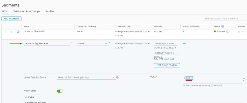
Create Segments in NSX‑T
Segments are Layer‑2 broadcast domains connecting workloads and uplinks.
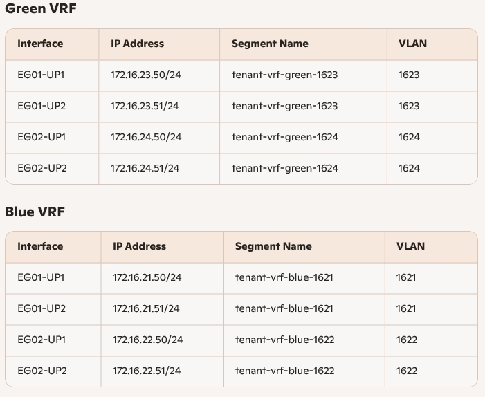
- Green VRF
tenant-vrf-green-1623→ VLAN 1623tenant-vrf-green-1624→ VLAN 1624
- Blue VRF
tenant-vrf-blue-1622→ VLAN 1622tenant-vrf-blue-1621→ VLAN 1621
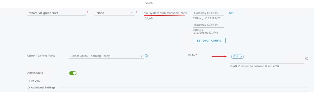
You need the second Uplink Segments ie : (external connectivity to physical routers) so we will define our second segment for our Green VRF on vlan 1623
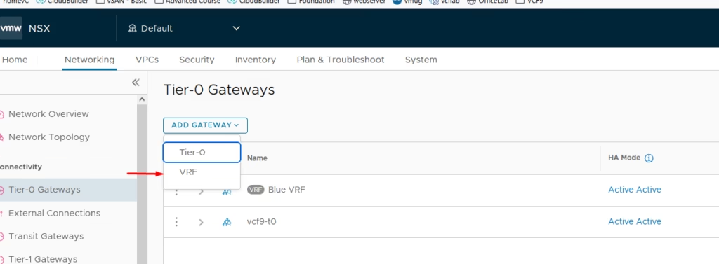
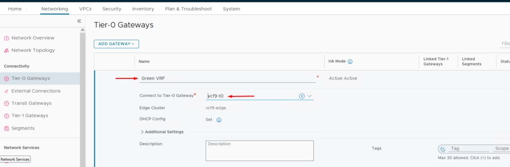
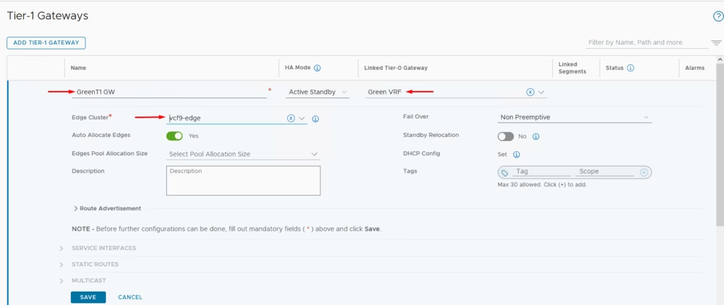
Create VRF Tier‑0 Gateways
Under Parent Tier‑0 Gateway, select Add VRF Tier‑0 Gateway.
- Define names:
Green-VRF - Assign Edge Cluster.
- Attach uplink segments.
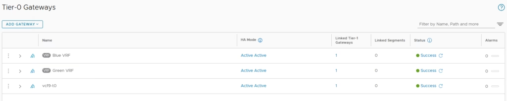
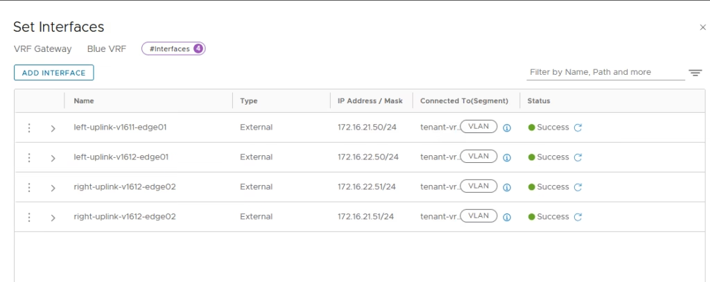
Repeat the same process for our Blue VRF
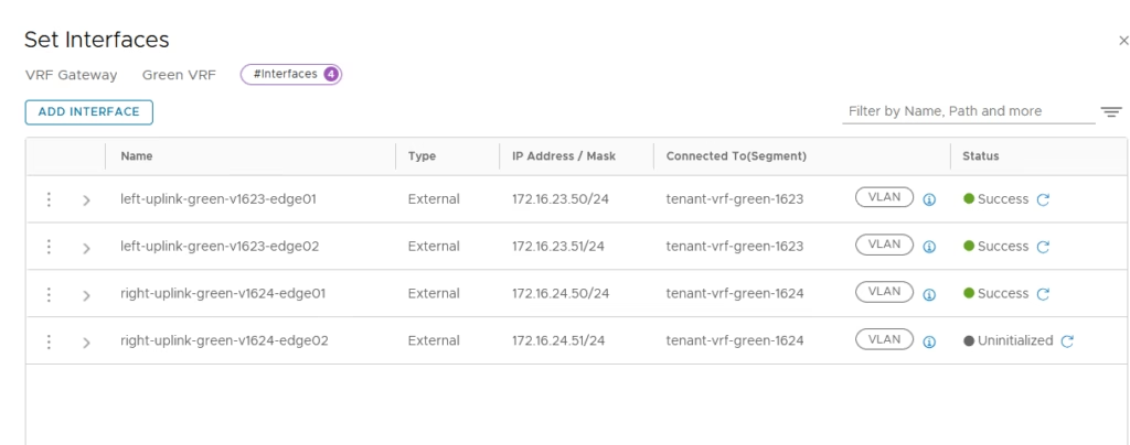
Configure Uplinks
Now that the VRF enabled on our Blue and Green Tier-0 Gateways I am going to configure the uplinks on both VRF enabled Tier-0 Gateways.
Each VRF Tier‑0 Gateway has four interfaces for redundancy.
Configure BGP on VRF Tier‑0 Gateway
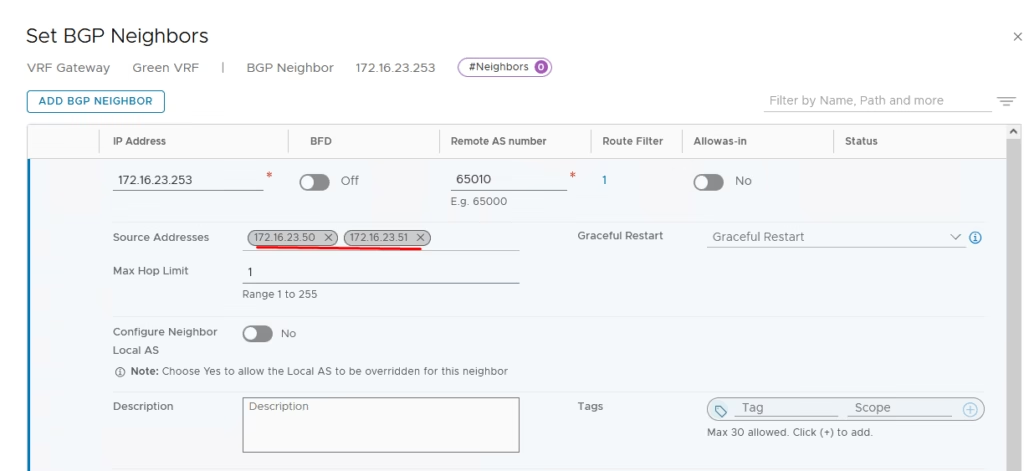
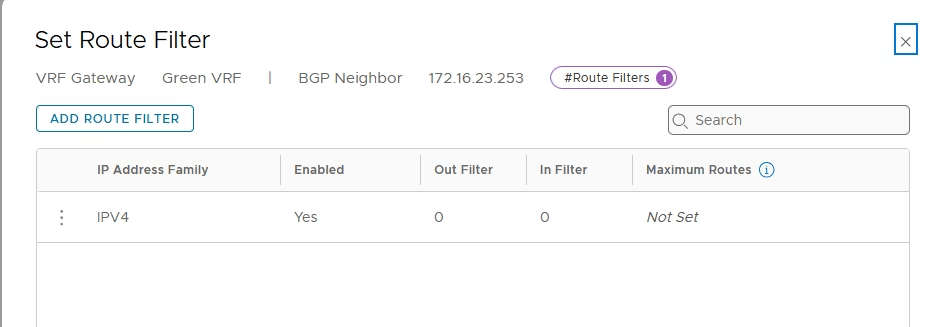
Add the route filter
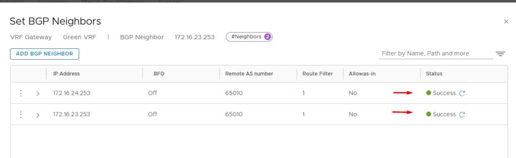
Add neighbours matching VyOS router IPs.
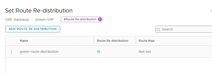
Provide a name for the route re-distribution entry and click on “set”.
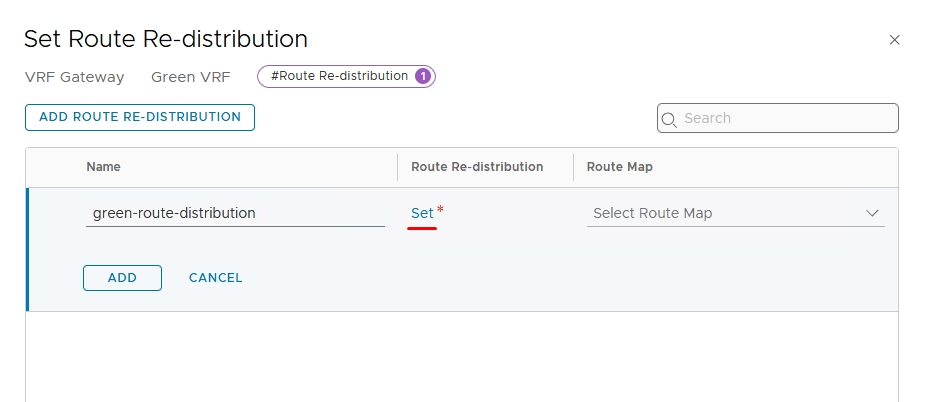
Configure route redistribution, Add entry → select Connected Interfaces & Segments.
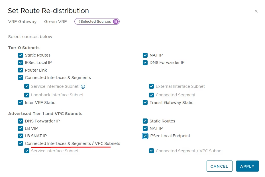
Apply and confirm entry is active
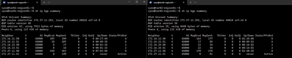
Login to our routers to verify if BGP Is working
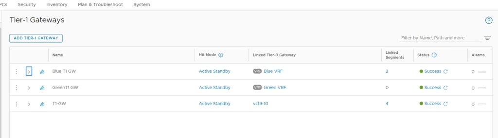
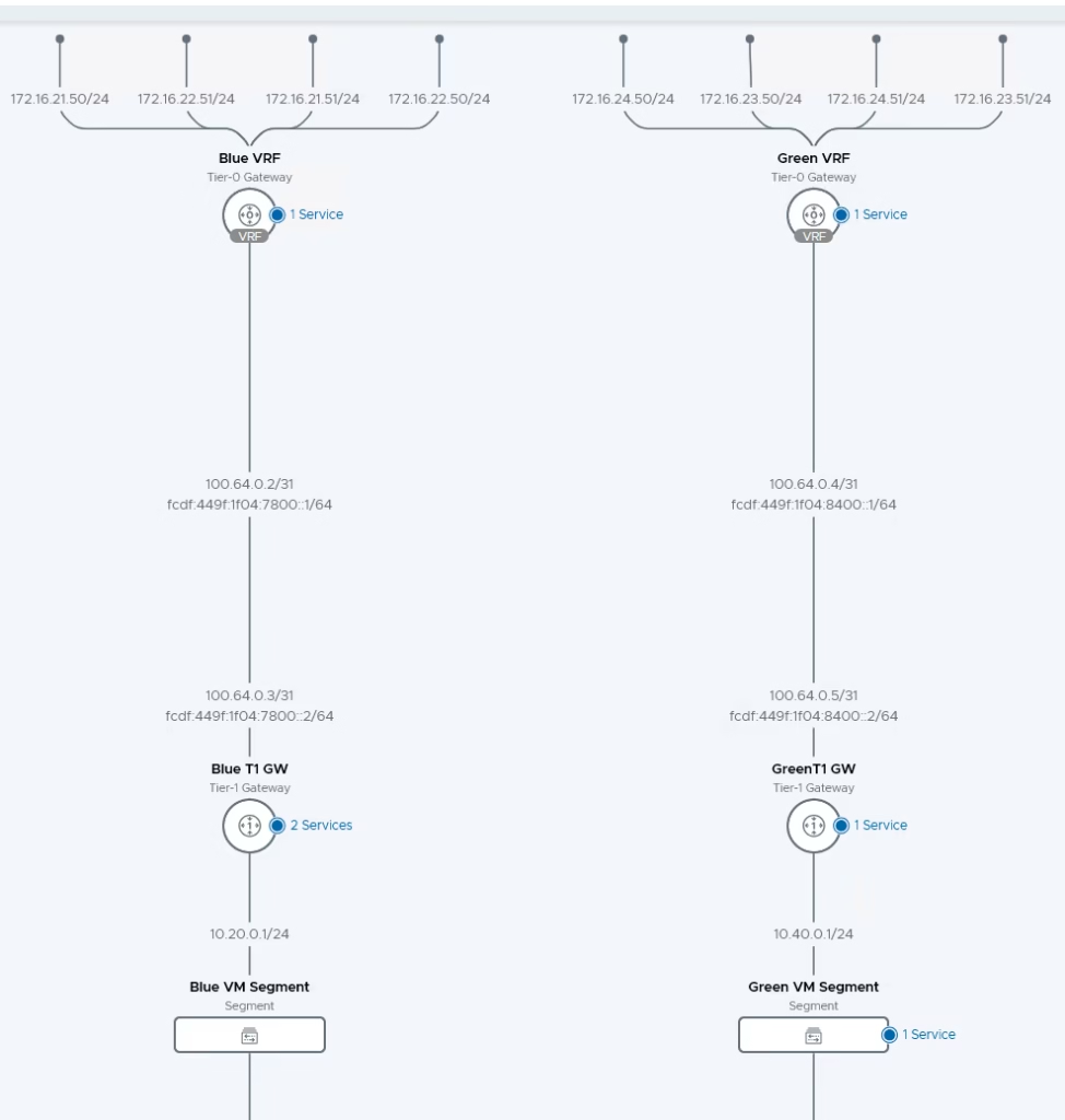
Create the T1 Gateway for our Blue and Green tenant
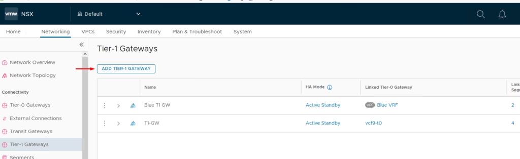
Attach it to the Tier 0 gateway we created earlier
Both the T1 Gateways are now created
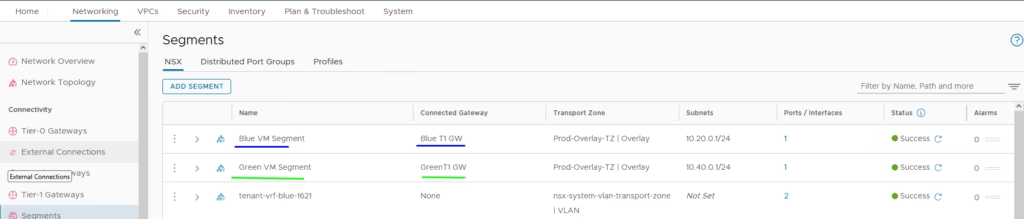
Add a Blue and Green tenant segment and connect to each of our new T1 gateways we created
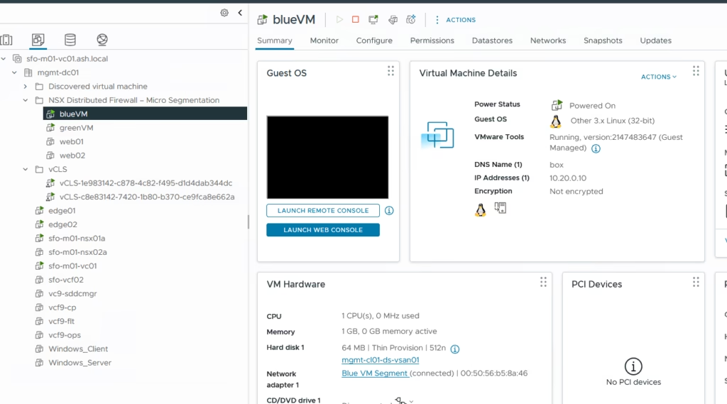
Create test Virtual Machines for Blue segment
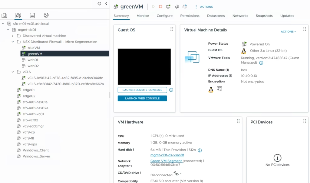
Create test Virtual Machines for Green segment
Perform some verification steps using CLI on the Edge Transport Nodes
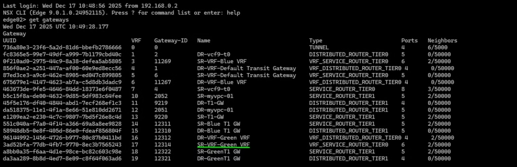
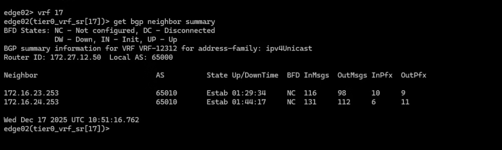
Login the service router on our Green VRF using VRF 17 and verify the BGP neighbour connectivity.
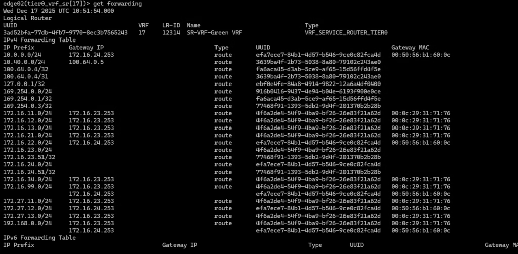
Routing table for this specific green tenant .
Verification steps using Traceflow on the NSX GUI
With VRF Lite, NSX‑T provides isolated routing domains under a single Parent Tier‑0 Gateway. By configuring uplink segments, BGP neighbors, and route redistribution, tenants (Blue and Green) maintain independent routing tables and connectivity to external networks. Redundant uplinks ensure resilience, while validation via CLI and Traceflow confirms operational truth.