
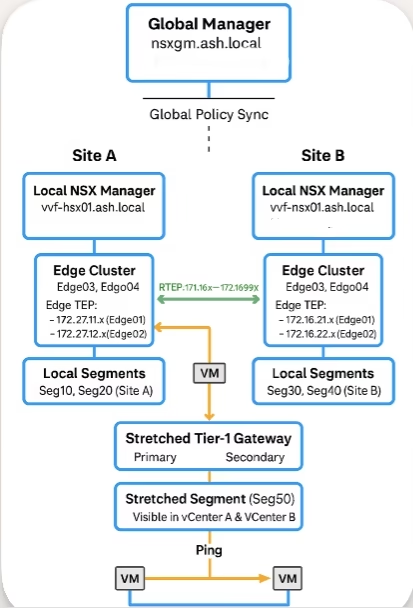
I will be working with two locations (Site A and Site B) and a Global NSX-T Manager to centrally manage the environment. For this, I installed a Global Manager after I deployed both Local Managers
NSX-T Federation allows organizations to extend networking, security, and policy management across multiple sites. With a Global Manager (GM) and multiple Local Managers (LMs), you gain centralized control, consistent policy enforcement, and seamless workload mobility — all while each site retains autonomy for local operations and failover.
This is especially useful in stretched deployments where unified visibility and compliance are critical.
Federation Architecture Overview
Global Manager (GM)
- Acts as the central control point.
- Manages global policies, universal objects, and multi-site configuration.
Local Manager (LM)
- Each site runs its own LM cluster.
- Handles local control plane and data plane operations.
- Syncs with the GM but remains autonomous for site-specific tasks.
Key Federation Components
The key logic of NSX federation is the introduction of an RTEP tunnel for VM’s across sites to communicate.
- Global Policies – Created centrally and replicated to all sites.
- Local Policies – Site-specific customizations when needed.
- Inter-Site Connectivity – Secure IP links between sites using RTEP pool or IP.
- Universal Objects – Tier-0/Tier-1 gateways, segments, groups, firewall rules.
Lab Topology
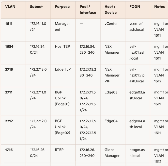
Site A – VLAN & Network Schema
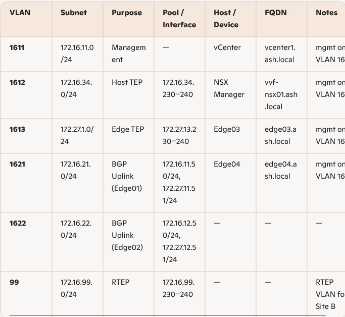
Site B – VLAN & Network Schema
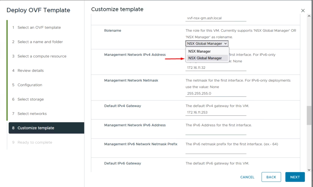
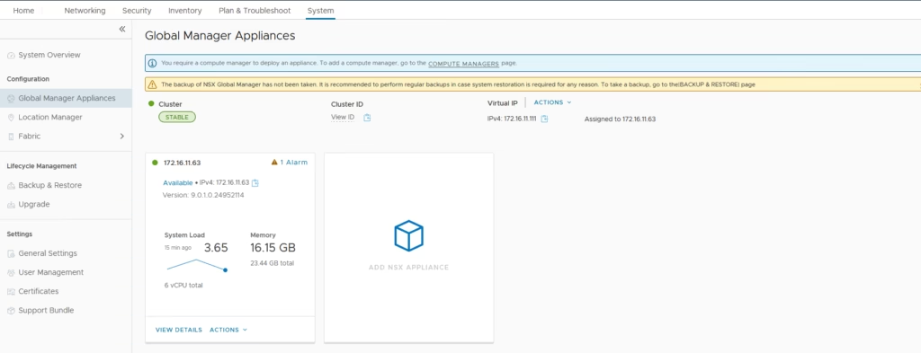
Deploying the Global Manager
The Global Manager deployment is nearly identical to deploying a standard NSX Manager — simply select NSX Global Manager during OVA deployment.
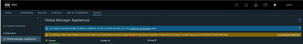
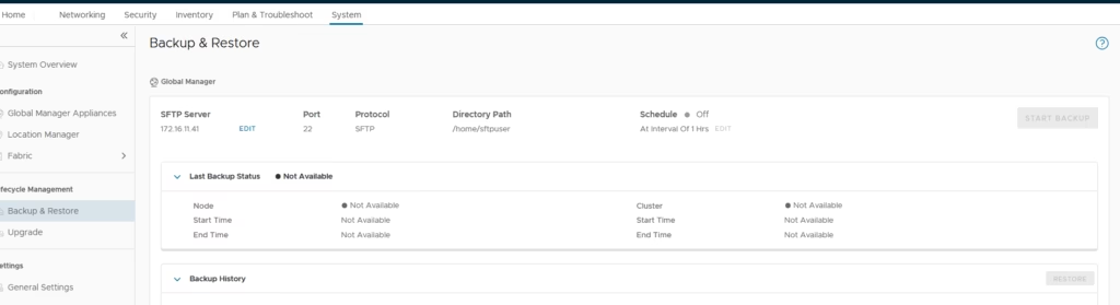
Before doing anything else, configure a backup target (SFTP in my case) and run an initial backup.
Perform a backup
Assign a VIP for the GM cluster to ensure high availability.
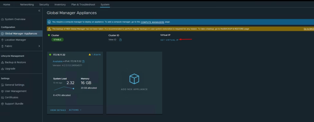
The VIP is now assigned
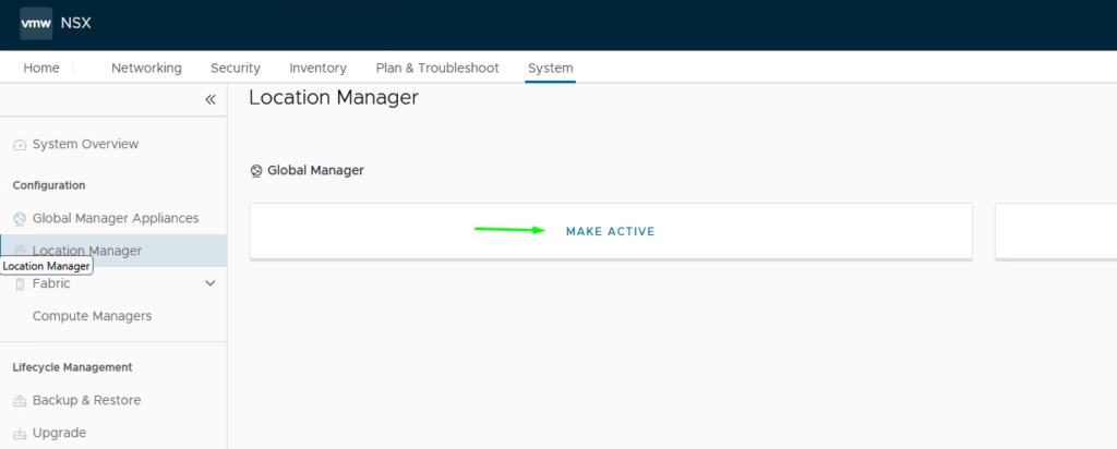
To Activate the Global Manager, Navigate to Location Manager, Click Make Active
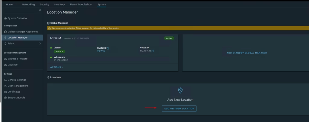
Provide a name and save

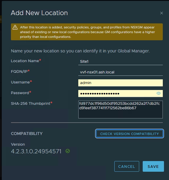
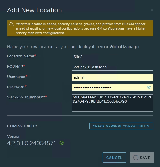
To Add our local On-Prem Locations to global manager, Click Add On-Prem Location
- Location name as Site 1
- FQDN/IP of the Local Manager VIP – vvf-nsx01.ash.local
- Credentials
- Retrieve the SHA-256 thumbprint from the LM
vvf-nsx03> get certificate cluster thumbprint
Mon Jan 12 2026 UTC 03:10:34.754
9dbc6c9f22452b75e24918f19fc139af6380255d3e3255b2f51b07bb4ff7eb46
Repeat for Site B.
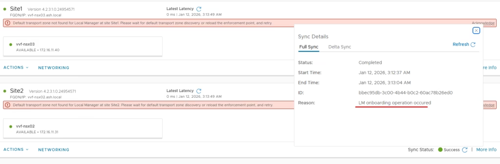
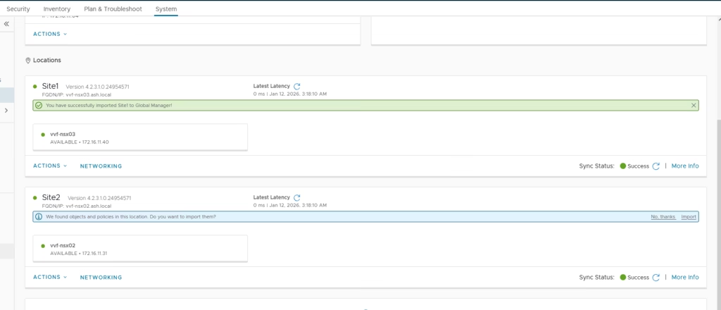
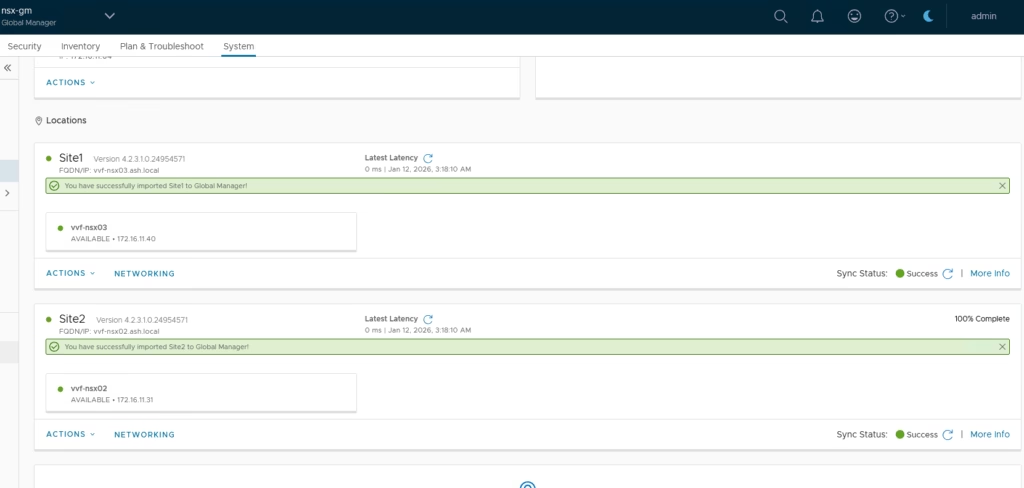
Once both sites are added, you’ll see sync status and site details.
Importing Existing Configurations
After the sites sync, import the existing objects from each Local Manager into the Global Manager.
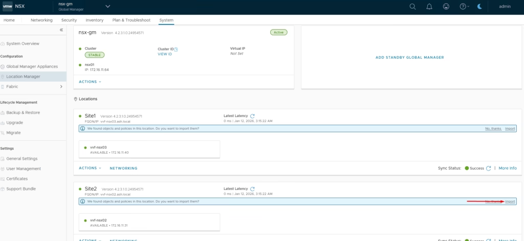
Select the site → Import
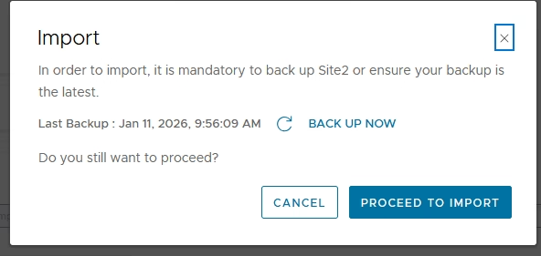
Apply a prefix (e.g., Site1) for easy identification

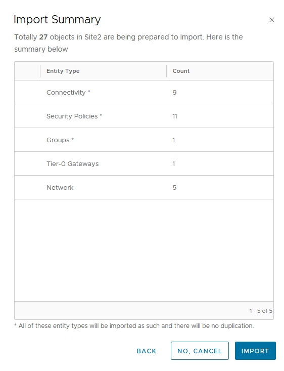
Review and import all objects
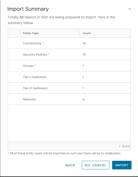
Once complete, all existing segments, gateways, groups, and policies become globally managed objects.
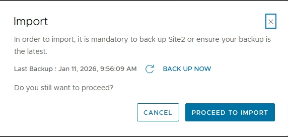
Repeat for other site.
Apply a prefix (e.g., Site2) for easy identification
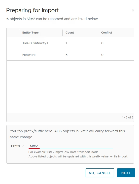
Once complete, all existing segments, gateways, groups, and policies become globally managed objects.
Finally sites are in sync
Configuring RTEPs (Remote Tunnel Endpoints
RTEPs enable cross-site traffic between Edge nodes. They function similarly to host/edge TEPs but are dedicated for inter-site Geneve encapsulation.
How does traffic flow between sites?
Traffic between VMs on different sites flows:
- From the host transport node > To the local Edge
- Through the RTEP tunnel to the remote Edge
- Finally to the destination VM on the peer site
Ok, lets connect to the local manager on Site 1 and go to Networking,Create IP Pools
Site A
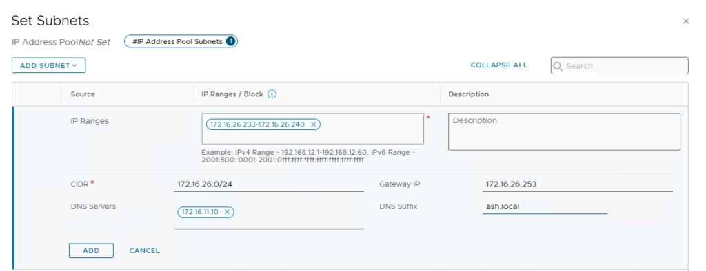
- Go to Networking → IP Address Pools
- Add a pool using subnet 172.16.26.0/24
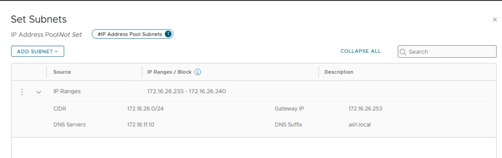
Finally click Save. Now repeat for the other Local manager/s
Connect to the local manager on Site 1 and go to Networking,Create IP Pools
Site B
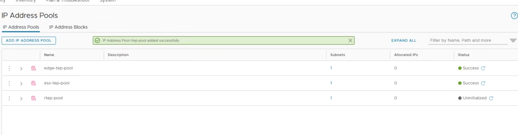
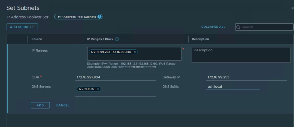
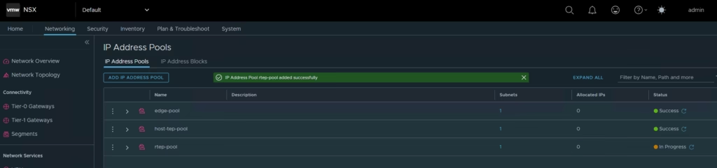
- Go to Networking → IP Address Pools
- Add another pool using subnet 172.16.99.0/24
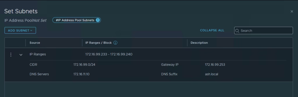
Finally click Save.
Configure RTEPs on Host
Site A uses VLAN 1626
Site B uses VLAN 99
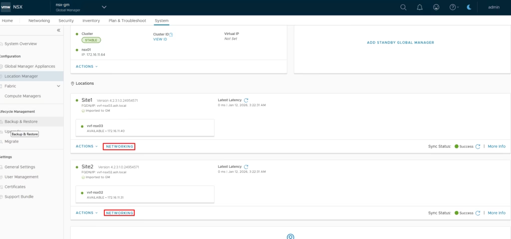
Go to Networking → Remote Tunnel Endpoint shows not configured

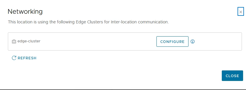
Go to Networking → Remote Tunnel Endpoint > Click Networking
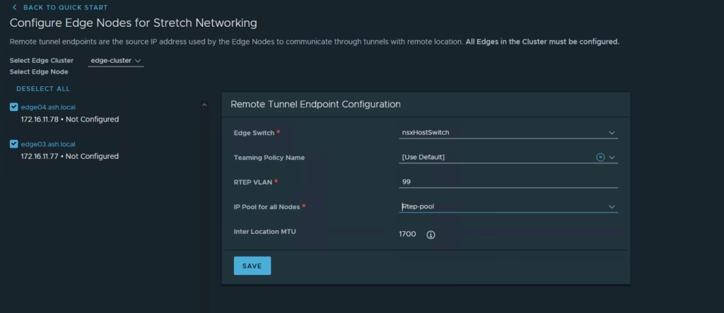
Click Configure
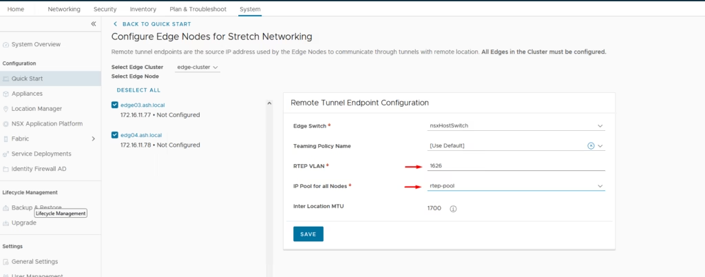
Select all edge hosts, choose the host switch and enter the RTEP VLAN and select the RTEP IP pool and Click Save
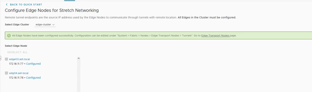
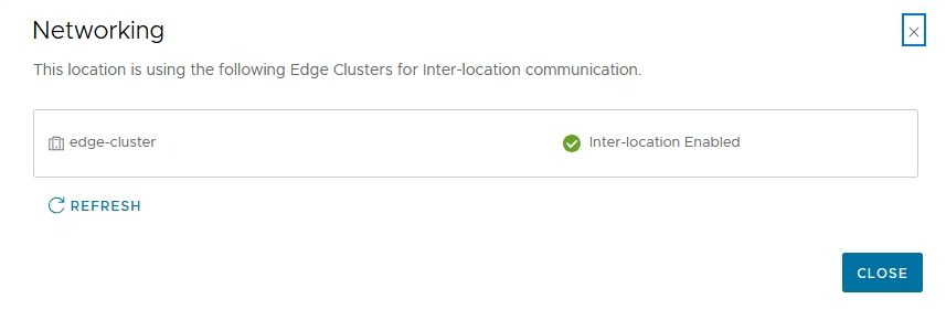
After applying, you should see confirmation that all Edge nodes are RTEP-enabled
Repeat the same for other site too , this time we will pick vlan 99
Lets jump over to our edge nodes and do a quick check.
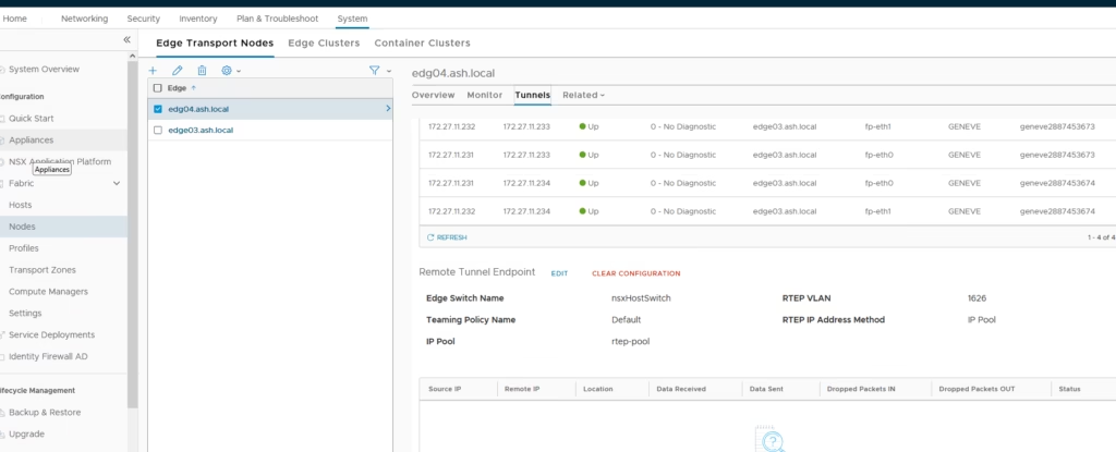
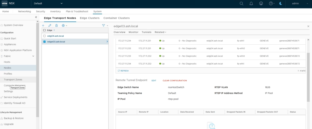
ok, so our edges are now rtep enabled
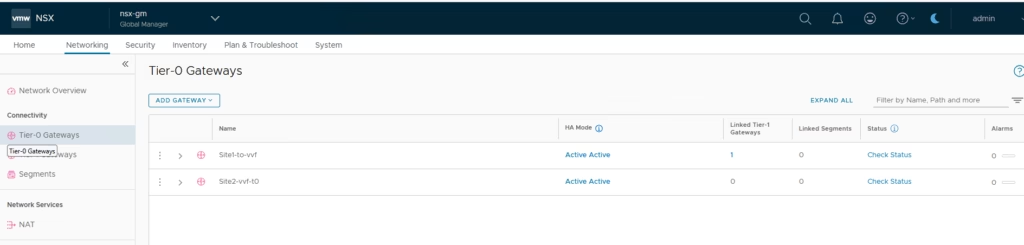
Back on the Global Manager, both T0 gateways appear
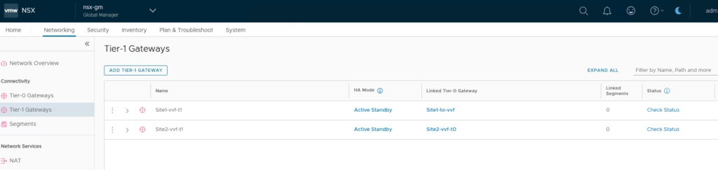
Both T1 gateways appear
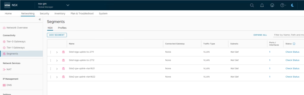
All segments from both sites are visible so everything is now centrally manageable.
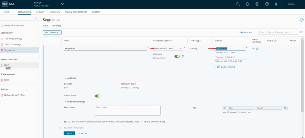
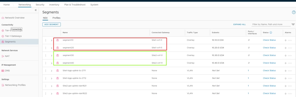
Creating New Segments Per Site
Site A
- Create Segment 10 and Segment 20
- Attach them to Site A’s T1 gateway
Site B
- Create Segment 30 and Segment 40
- Attach them to Site B’s T1 gateway
All four segments deploy successfully.
Creating a Stretched Tier-1 Gateway
To enable stretched networking across both sites:
Go to Global Manager → Networking → Add T1 Gateway
Configure:
- Primary Location: Site A (select Site A Edge Cluster)
- Secondary Location: Site B (select Site B Edge Cluster)
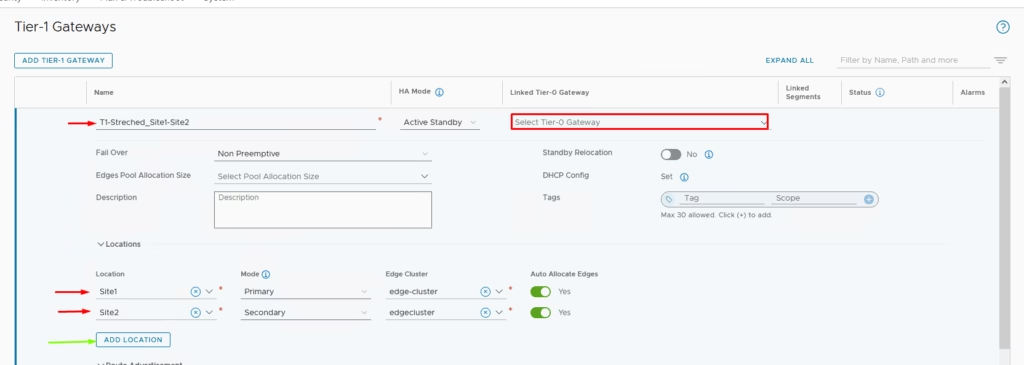
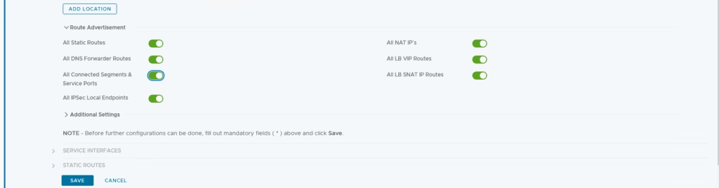
Enable route advertisement
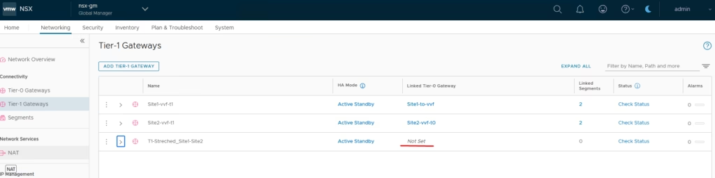
The stretched T1 is now created and ready.
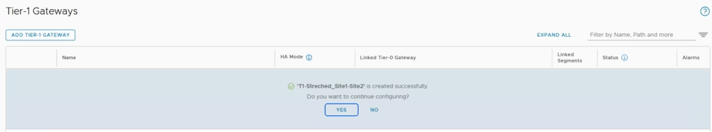
The stretched T1 is now created and ready for use , do note the linked T1 is set to none and that’s correct.
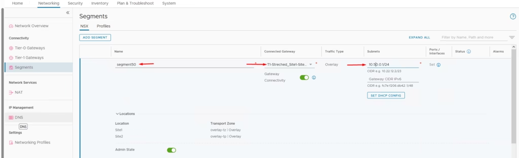
Add a Stretched Segment
Create Segment 50 and attach it to the stretched T1
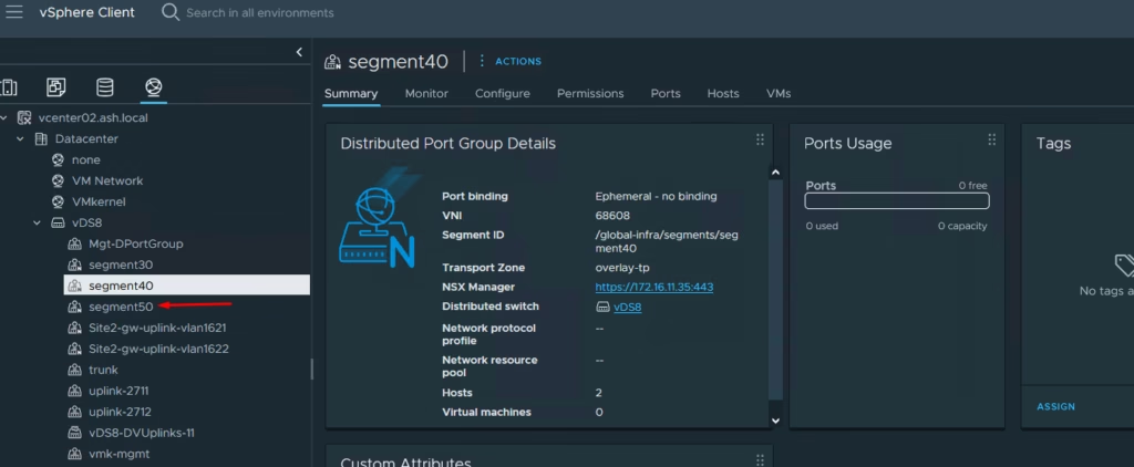
You’ll now see Segment 50 in vCenter Site A
You’ll now see Segment 50 in vCenter Site B
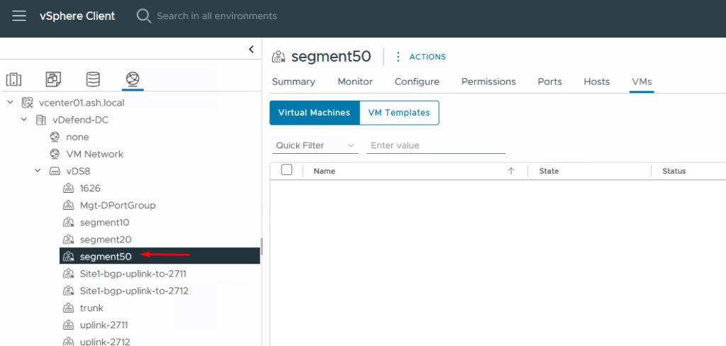
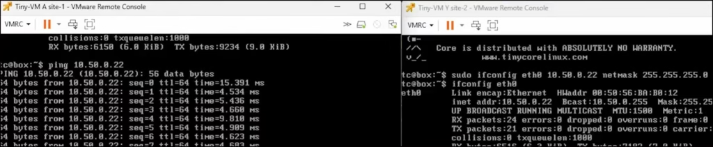
Deploy a VM on each site on Segment 50 — cross-site ping works as expected.
Important Operational Note
Once configurations are imported into the Global Manager:
- Any new changes must be made from the Global Manager
- Local Manager changes will not sync upward
That’s the complete setup of NSX-T Federation in my lab.